RC Rover - Gidget
Designed, prototyped, and tested an RC rover that can traverse diverse and challenging terrain, and pick up objects of various shapes and sizes before returning to the initial 16”x16” starting area
Overview
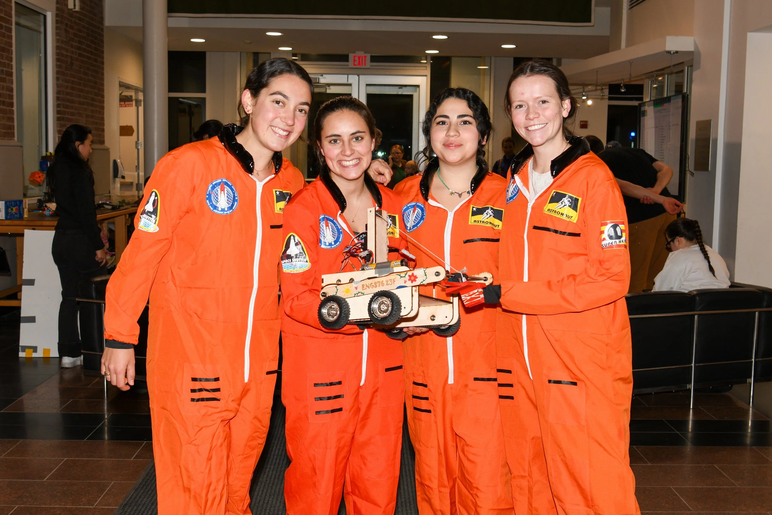
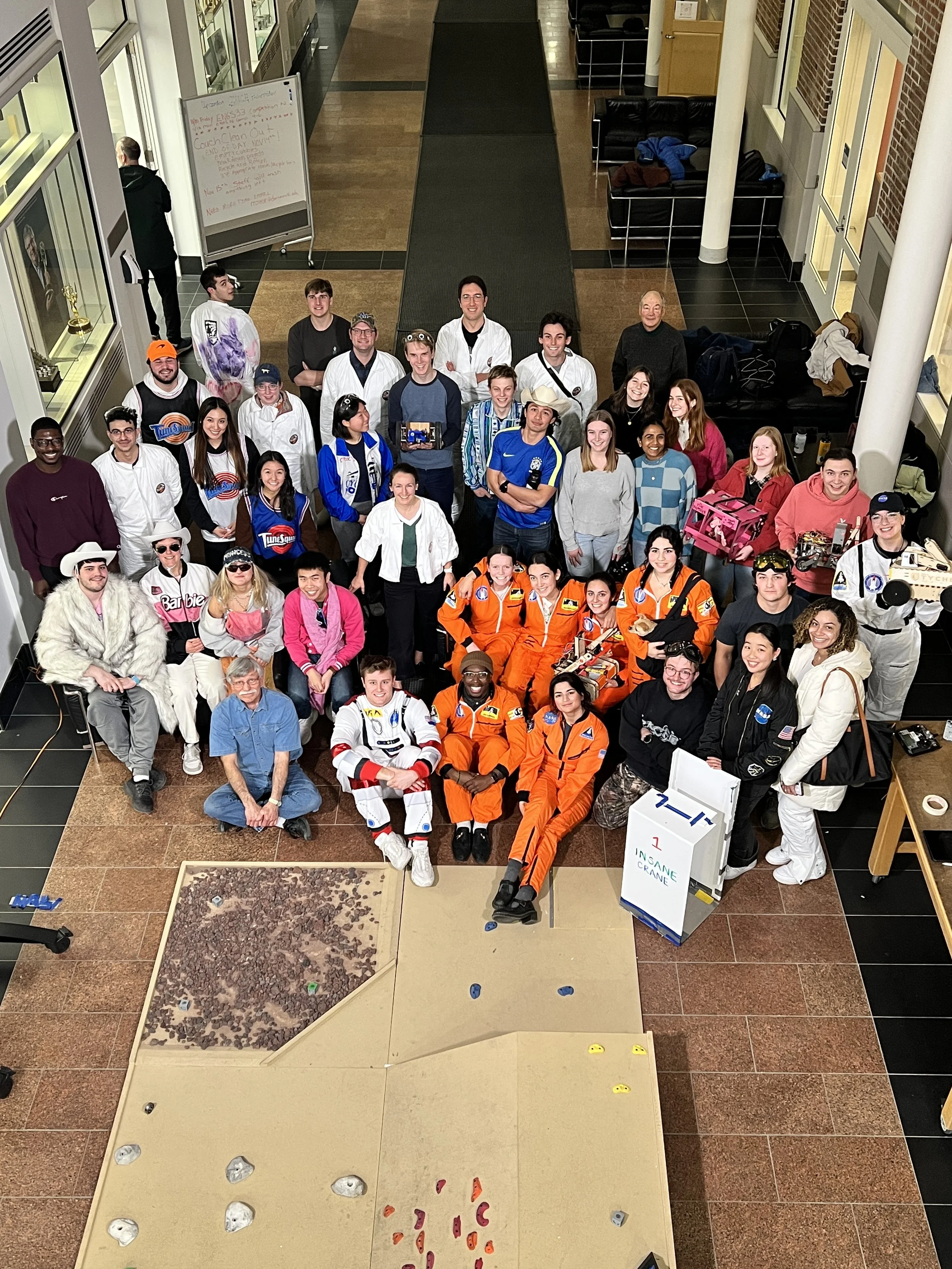
The Machine Engineering course at Thayer (ENGS 76) has a project component where groups of 4 people have to design, prototype, and test an RC rover. This year’s challenge, ‘The Mars Rover Mission’, included options to pick up and store multiple objects and hold their weight, drive up a slanted surface that is at a ~27 degree angle, travel through a gravel field, climb up a hill with boulders on it, and ascend and descend a cliff. Teams were allowed to design their rover for as many or as little of these components as they wanted. My team chose to focus on picking up and storing objects, navigating the gravel field, ascending and descending the cliff, and climbing up and down the plain part of the hill. So, our rover, Gidget, was designed according to these specifications using the CAD software SolidWorks. Before starting to construct it, we performed FEAs, stress/strain calculations, and center-of-mass tipping calculations. After the analysis stage, we relied on laser-cutting, 3D-printing, lathe, milling, sanding, and gluing to assemble our rover. Gidget and our team went through 3 design reviews before the competition: an SRR (System Requirements Review), PDR (Preliminary Design Review), CDR (Critical Design Review). We received helpful feedback during these design reviews, and our team came 2nd out of 9 teams during the final competition.
Design Considerations
Below is a summary of some of our design considerations while prototyping:
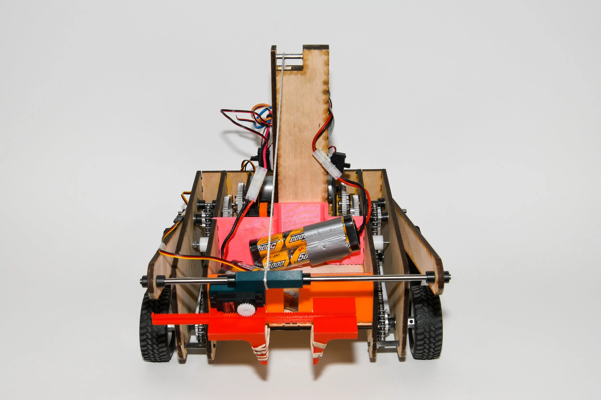
Multiple gripper mechanisms were considered by our team. The “elbow” gripper arm offered a precise gripper placement but required more servos than other options and was prone to buckling/bending. Another option was to have the gripper rotate about the z-axis and drop an object into a storage bin located on the rover. Our concern with this design was that we would not be able to actuate rotation about the z-axis while also ensuring that the gripper is stably and reliably held. We ultimately decided to adopt a four-bar linkage equivalent and have two arms (connected to the chassis) lift the shaft that the gripper would be moving along. One of the gripper fingers would be stationary on the shaft and the other would be sliding. For stable and simple actuation of the vertical motion of the gripper, we decided to glue a rope to the shaft directly and spool the rope in a stem structure that would sit roughly in the center of the rover. The gripper—and the rover arms—lift when the rope is spooled and get lowered when the rope is unspooled.
The design of a storage component was essential to be able to carry and not drop the objects collected throughout the course. We originally wanted to have a moving storage component that acted like a drawer, to store the cubes in a way that did not necessitate the gripper to move back and forth. Upon more prototyping and analysis, we realized that this way of storing cubes would be very time & space-inefficient and would require more servos. We then pivoted to having a stationary storage box that sits on the chassis. After receiving feedback from our Professor, we went from wanting a box to sit on the chassis to just building walls and leaving the space open.
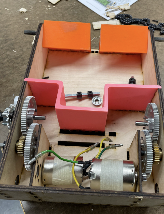
Our chassis design also changed throughout the project. Initially, we had just three sides of a box to make up the chassis. After looking at the course and initial modeling, we decided to move the baseplate upwards to clear the boulders on the game-board. Additionally, we added teeth to stabilize the assembly of the boxes. We also added two side plates on each side to make sure the axles were more stable and that our gearbox was protected.
Various steering options were considered early on in our design journey. We ultimately decided to pursue tank steering over a differential mechanism, two-wheel-drive, or four-wheel-drive because it allowed for the best maneuverability of the course while maintaining a simple design that we could complete in 8 weeks. The implementation of tank steering also simplified our design because we did not need suspension; any time the rover would need suspension to get off of a boulder or over bumpy terrain, the flexibility afforded to us by implementing tank steering allowed us to navigate over any obstacles. Because we valued stability in our rover and knew how effective 4 wheels are on all cars, we pursued 4 wheels instead of 2. For our tank steering design, we decided to use a chain and sprocket system to make the left wheels turn in the same direction and speed, and the right wheels turn in the same direction and speed. We ended up adding an idler to this three-sprocket system so that we could manually tighten the chain after assembling the system.
We performed several gear ratio calculations for the drive, the gripper itself , and the stem which we used to elevate and lower the gripper.
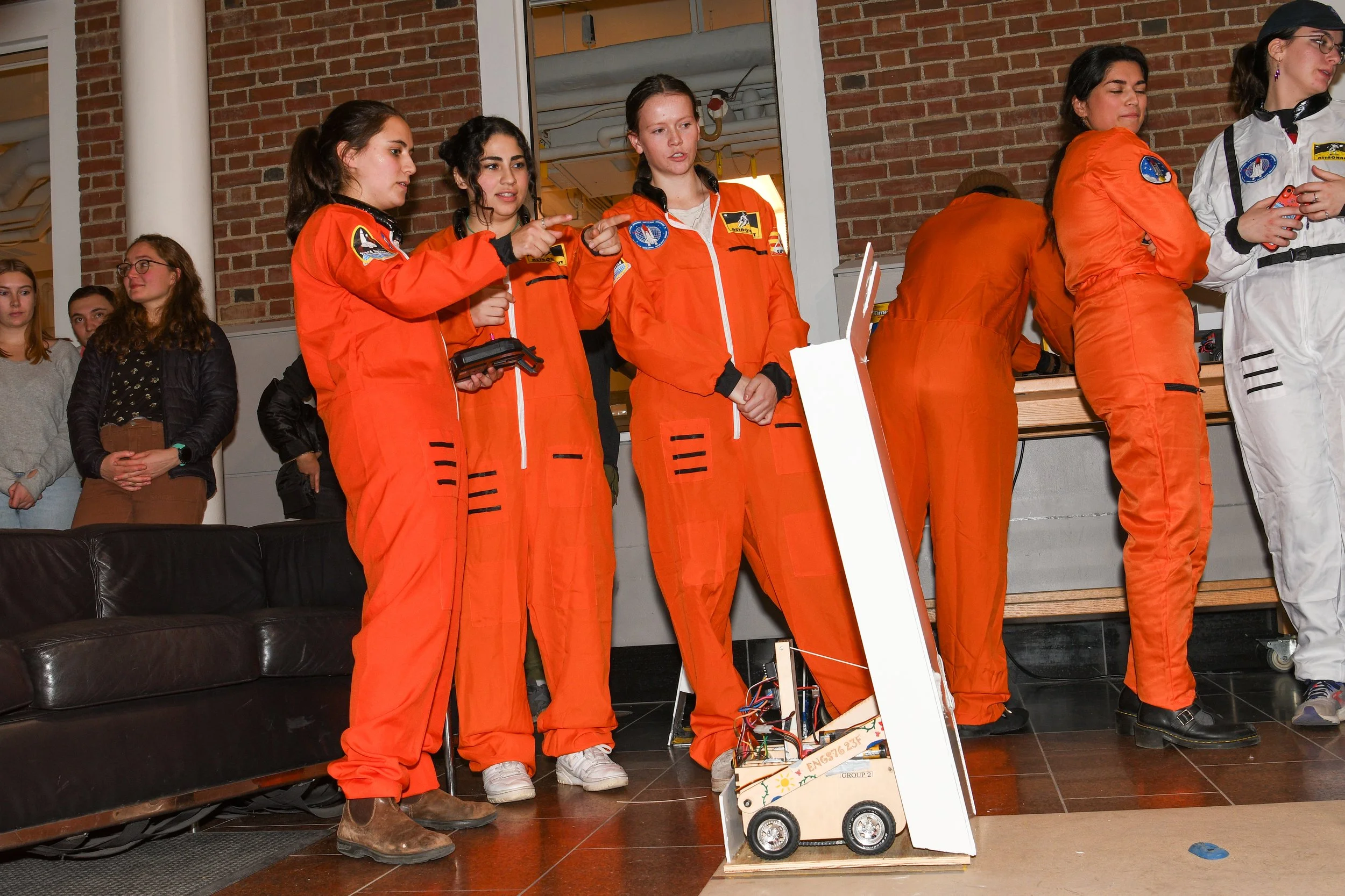
We ended up designing an extra ramp that that can be extended and collected back to fit into the starting/finishing square, to help us ascend and descend the cliff. We utilized our rover’s gripper arms to push this ramp open so that it virtually serves as a bridge point between the cliff and the starting square. At first, our strategy for folding the ramp back up was to push it from behind using the rover gripper arms. However, upon trying this strategy a couple of times we realized that it was not going to work out. We, then, came up with the idea of connecting ropes to the ramp that our rover could grip and pull on. We went through a couple of prototyping cycles where we played around with which objects we could attach to the ropes for our rover to more easily grip on them, what height these ropes should be connected to the ramp at, and where the object should sit on the base of the ramp. After a couple of iterations, we concluded that gluing a power cube that sits slightly to the left of the center of the base gave us the best results.
Implementing our design and assembling our rover was as challenging as the design process itself. We had to make many manufacturing decision, and in some cases slightly pivot, especially when constructing the rope spooling mechanism, the stem sub-assembly, the gripper servo mount, the front storage wall, and the back storage wall.
Takeaways
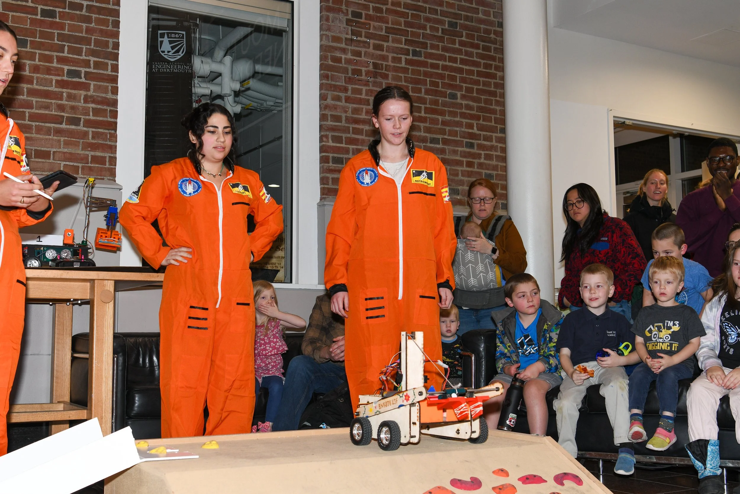
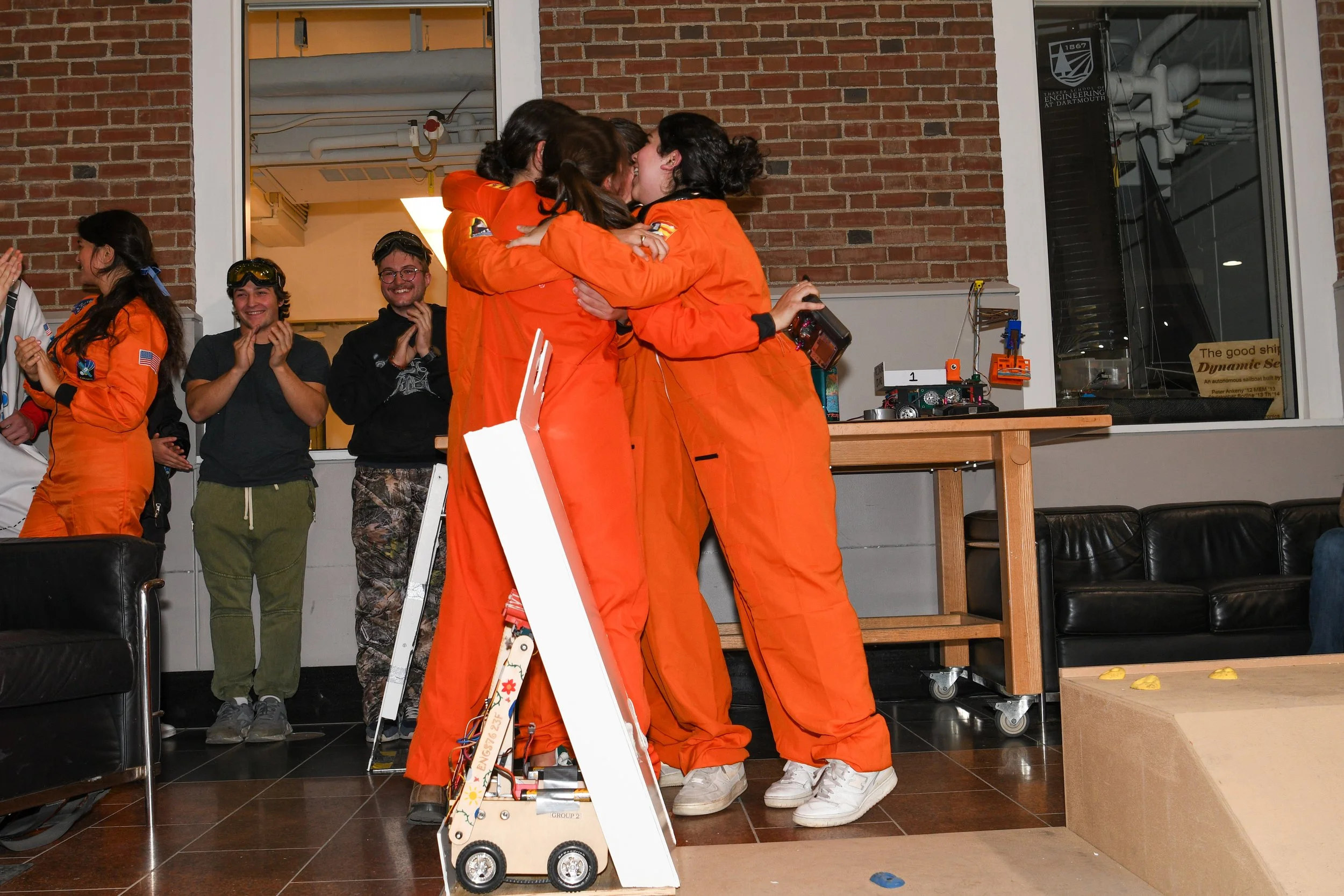
Our team's rover demonstrated a reliable and successful performance at the competition. We were able to complete almost all the tasks we set out to do. It was incredibly rewarding to showcase our rover. The most notably awesome moment was when our rover was able to close the drawbridge in the final five seconds of the competition. In a dramatic, movie-like fashion, it was pretty down to the wire. At that moment, all our hard work had paid off and it was incredibly special to experience that together as a team, surrounded by our classmates and friends.
There was only one incident in which the chain fell off the sprockets when the rover was driving in the rocks. This had never happened before in practice, but after assessing the situation it was clear that the idler had become loose. If I had the opportunity to change our rover again, I would choose to stabilize the idlers better by screwing them into the outer wall. I would also make adjustments to the size of the slot that the idler moves in. We initially designed it slightly small to sand it until it was the proper size. However, this led to some obvious human errors as the slots were too big and the idlers moved too much. In the future, I also will make sure that all components are screwed in tightly before a competition or performance assessment. Similarly, once we were done making final changes to weight, we re-measured the weight of our rover and re-calculated our ideal gear ratio and gearbox. The new, more accurate gearbox was slightly different from the current gearbox we had designed. However, our rover was driving very well and able to go up and down the ridge pretty consistently. Because of the time constraints of the class, we collectively decided not to make changes to our existing gearbox, despite the calculations. However, if I were to make changes in the future this would be one of them. This also may have allowed our rover to have enough torque to drive up the rocky ridge.
From the gripper sprint to putting the finishing touches on our rover, I learned a lot throughout this process. Being able to make things out of foam core to test ideas, or jumping into CAD to visualize concepts allowed us to propel our design forward. The CAD capabilities I acquired are an essential engineering skill that I will be able to build off of in future endeavors. Additionally, being able to precisely document our work with drawings is an important skill as we work on future projects beyond Dartmouth. Specifically, it was a good experience working in an assembly with a team of other engineers and making sure parts fit together correctly even though they have all been made by different people. I learned the importance of having a naming convention for parts so that they are easy to find and keep track of. Another key skill I gained was being able to participate in design review meetings by communicating our ideas and leveraging feedback to further advance our project. An essential skill I learned throughout the process of drawing, machining, and assembling was assigning tolerances to different parts. This became especially important for parts that are press fit, like the bearings into our chassis, which we ended up having to re-laser cut to adjust the bearing holes. For parts that were made with the laser cutter, different faces of the wood had different fits, which was important to consider in our assembly.


