Truss Bridge
Used CAD and FEA to design a truss bridge constructed out of plywood; came 1st in Instron Machine compression testing competition
Overview
The Solid Mechanics course (ENGS 33) at Thayer had a project component where groups of 6 people had 6-7 weeks to design truss bridges with the goal of withstanding the most amount of force in an Instron Machine competition to be held at the end of the term. The project was constrained not only by time but also by material usage. Upon being designed using CAD software, our bridge had to be manufactured out of 3mm and 6mm plywood sheets, and we were not allowed to laser-cut parts for our bridge more than once. So, my group spent a lot of time performing FEAs and modifying our design to minimize displacement, buckling, stress, and strain. There was a weight limit on the bridges and lighter bridges were to receive more points so we had to navigate a trade-off between strength and material usage. My group’s bridge ended up withstanding the most force (6.15 kN) and therefore placing 1st in the competition out of 8 teams.
Design Considerations
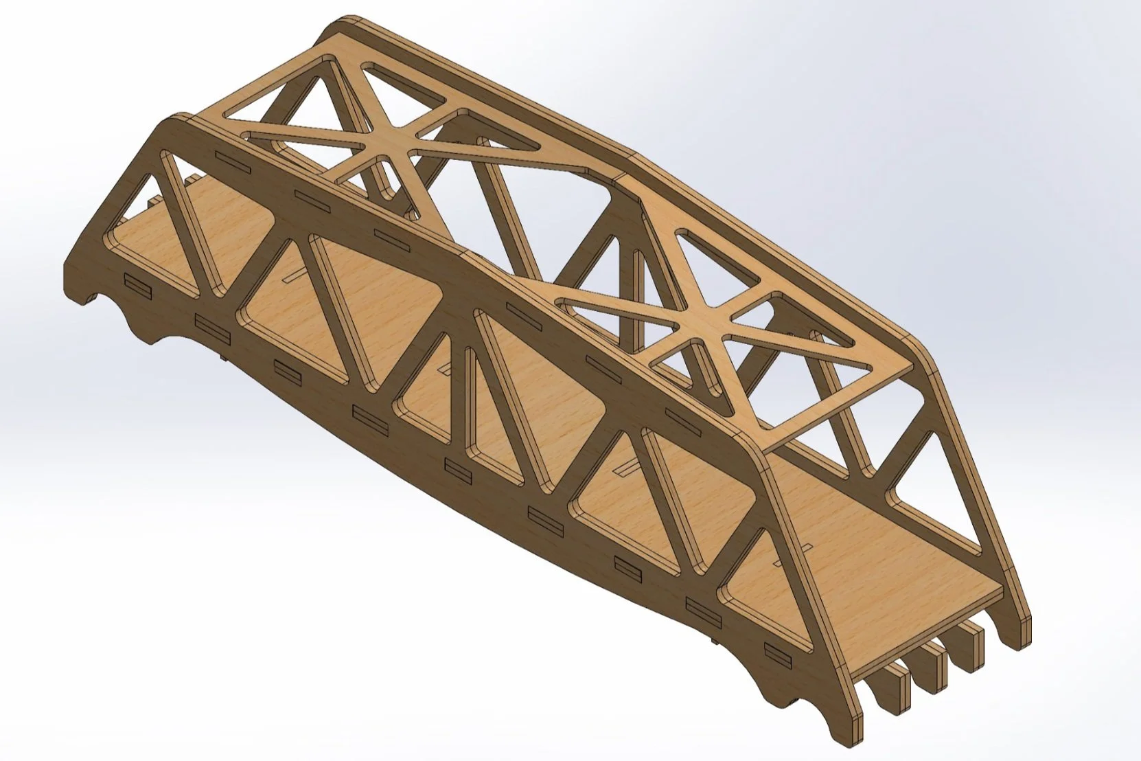
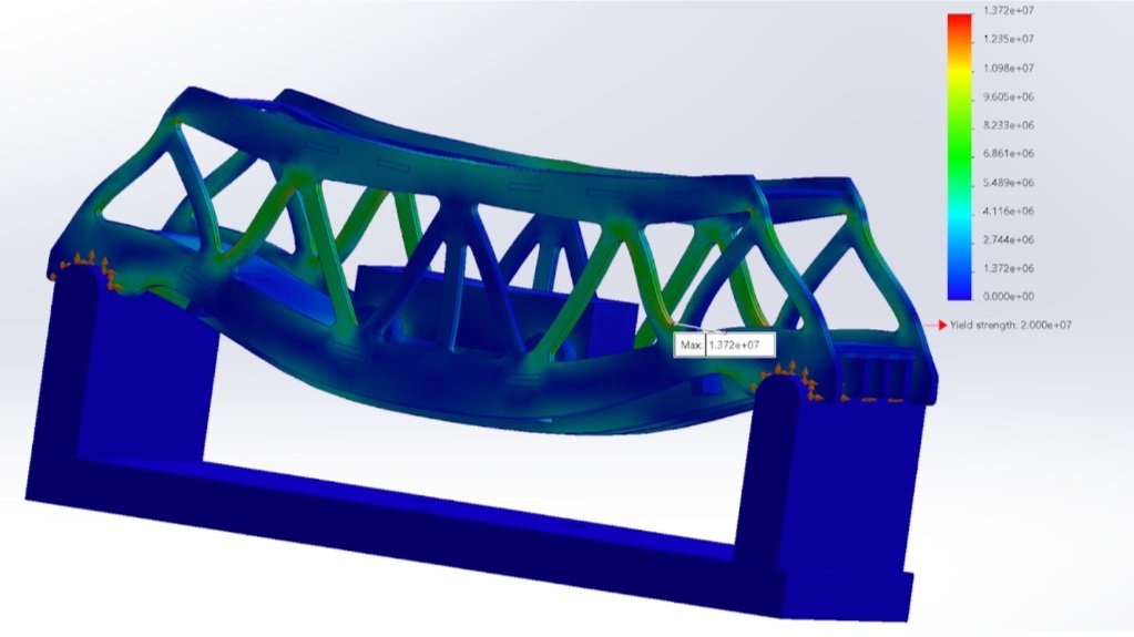
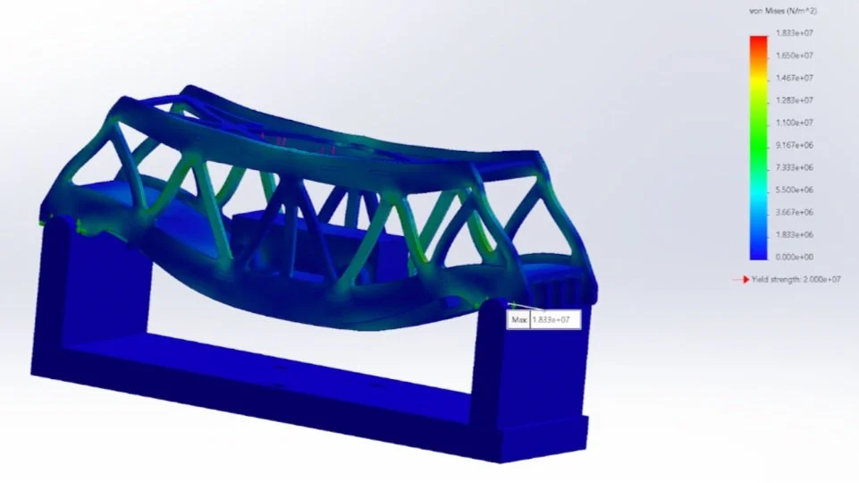
Our team’s design process was highly iterative. We began by reviewing basic bridge structures studied in class, researched real-world bridges that have held strong for years, and did our own brainstorming. We ultimately decided on using the Warren bridge as our base design to make modifications on, primarily due to our knowledge of equilateral triangles and their ability to spread force more evenly across members. We performed FEA analyses often and made adjustments accordingly. Looking at the stress and displacement FEA diagrams, we would decide on a specific improvement that we could make to decrease stress or displacement in a specific area. After making a design change, we would re-run the FEA, and decide if the adjustment was beneficial by comparing maximum displacement and stress values from various levels of applied force. We went through a total of 16 iterations; below is a list of our most important design considerations:
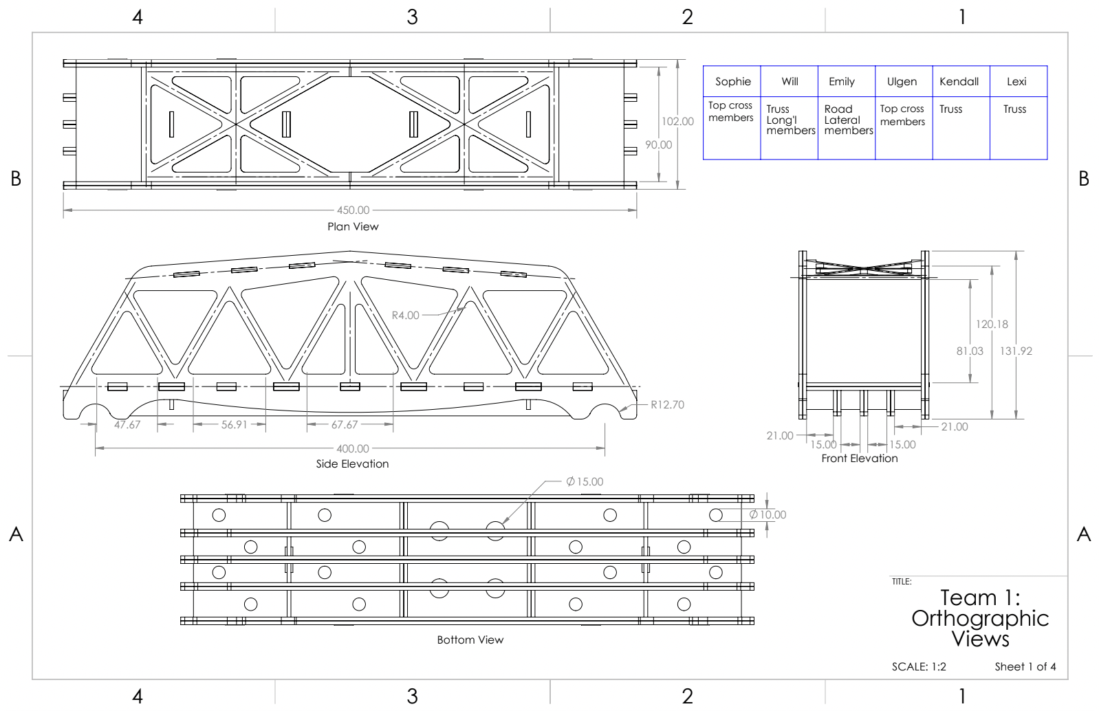
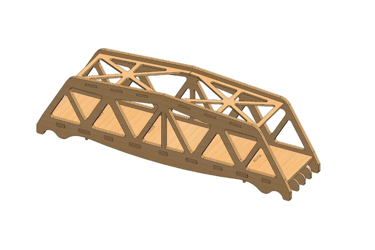
Cross members on top of the truss were key to preventing the buckling of the two trusses. So, we tested several different cross member designs on our bridge using SolidWorks simulations.
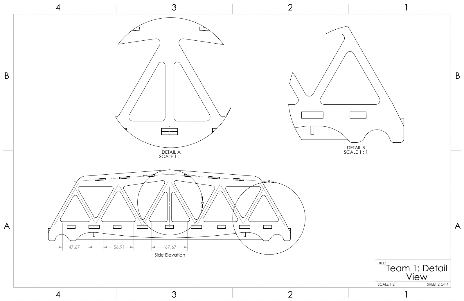
Adding a vertical member to the center triangle was crucial to prevent buckling even though this member did not experience significant stress or strain.
Thickening the member width of the 2nd and 4th triangles from the left side of the bridge proved to be an absolute necessity based on several of our FEAs.
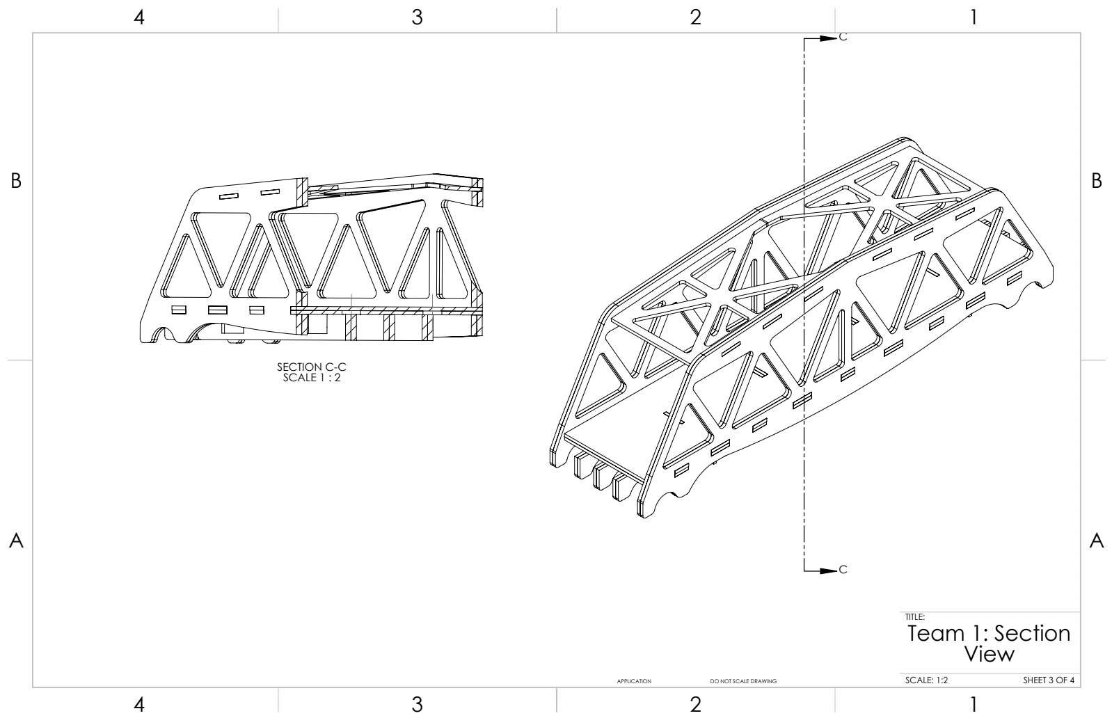
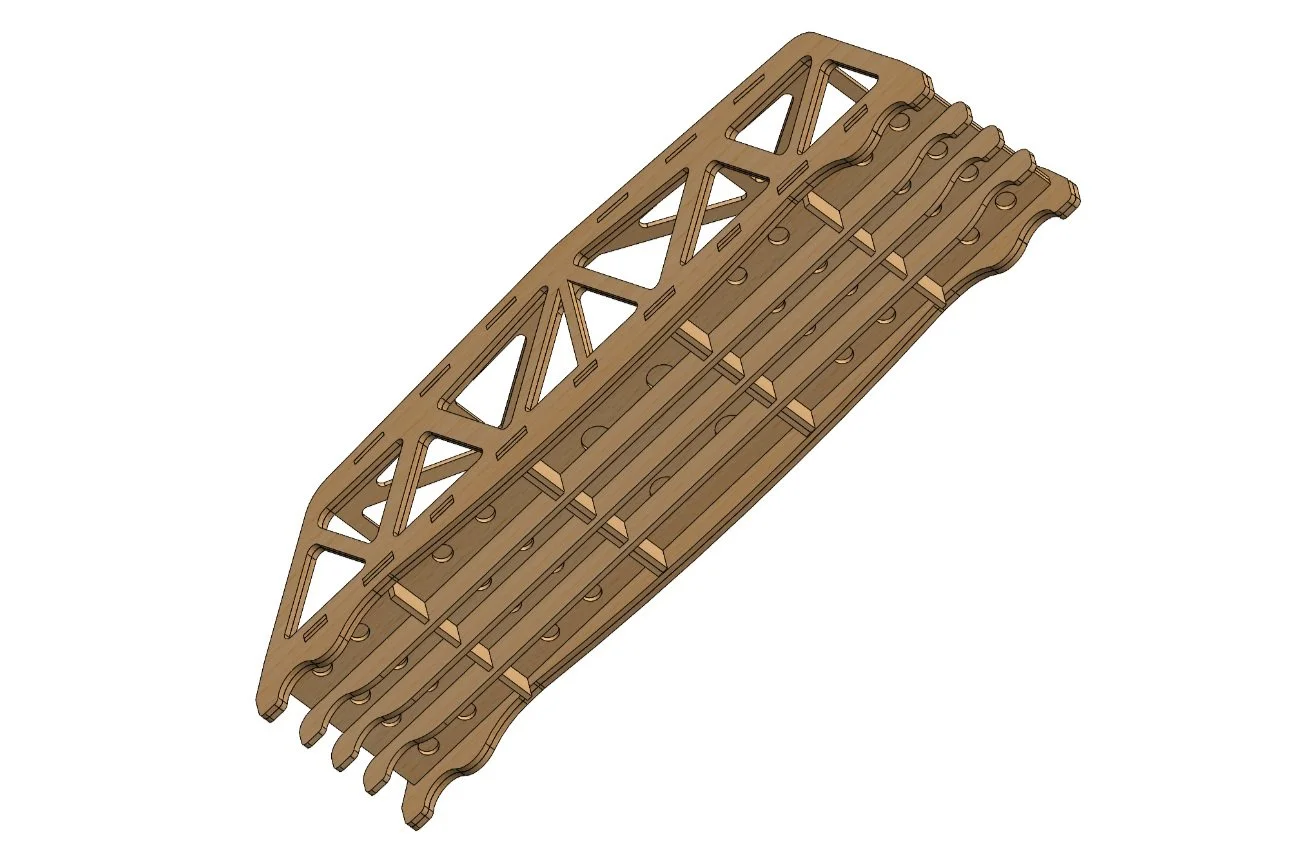
Gluing two 3mm pieces of wood together rather than using a single 6mm layer was a conscious choice we made to increase the strength of our bridge with the aid of the glue. This was a simple yet effective intervention we were able to make by thinking about manufacturing during our design process.
Increasing the fillet radius of the part of the bridge that rested on the jig (which we colloquially called the “hook”) was beneficial for decreasing the stress concentration. At first, we used the industry standard 1/8th inch radius for fillets on all corners of the bridge, but soon realized that being more intentional with the fillet radius in areas where the FEA showed a higher stress concentration would work to our benefit.
Minimizing material usage of our design was important. To maximize the strength-to-weight ratio of the bridge, we worked to find places where the stress concentration was minimized, and reduced material in these areas. For example, we noticed that although having two layers of road was helpful for supporting the bottom of the truss and the longitudinal members, the second layer of road was not experiencing significant stress in any specific area. As a result, we cut circular holes in the road which reduced the weight of the bridge and had negligible effects on its weight bearing capabilities. We also used 3mm wide longitudinal and lateral members instead of 6mm.
Takeaways
The analytical predictions we made before the competition were somewhat accurate.
The deflection we predicted at 2kN of force was 1mm and our bridge deflected by 1.24mm. The displacement we predicted was inaccurate compared to the initial displacement in the Instron test because the bridge did not rest evenly on the jig. Therefore, once minimal force was imposed on our bridge, it experienced significant ‘deflection’ as it settled onto the jig. This error can be attributed to issues with construction. To improve accuracy, we would need to assemble the bridge perfectly, and sand-down all points of contact, until the bridge sits evenly. Another option would be to slightly offset the force from the center when performing an FEA, to more accurately observe changes to stress and strain computations
Our maximum force prediction was 7.5kN and our bridge withheld 6.1456kN. This discrepancy could also have resulted from FEA assuming perfect construction, with all members completely meshed together. Moreover, the Young’s Modulus for Baltic Birch plywood that we calculated had lots of variation between groups. Ideally, a more accurate spec about our specific pieces of birchwood would improve our predictions of bridge deflection.
Lastly, we predicted the location of the failure correctly as the second triangular panel from left within the truss. However, our predicted mode of failure was tensile fracture but this panel actually failed due to buckling. We were able to predict the location of failure precisely due to the concentration of stress shown in multiple FEA tests. In order to address this weakness, we had increased the width of the said members but evidently this was not sufficient.